ECE153B_Final_Project
Cycling Sensors
By Thomas Stubbs
Project Overview
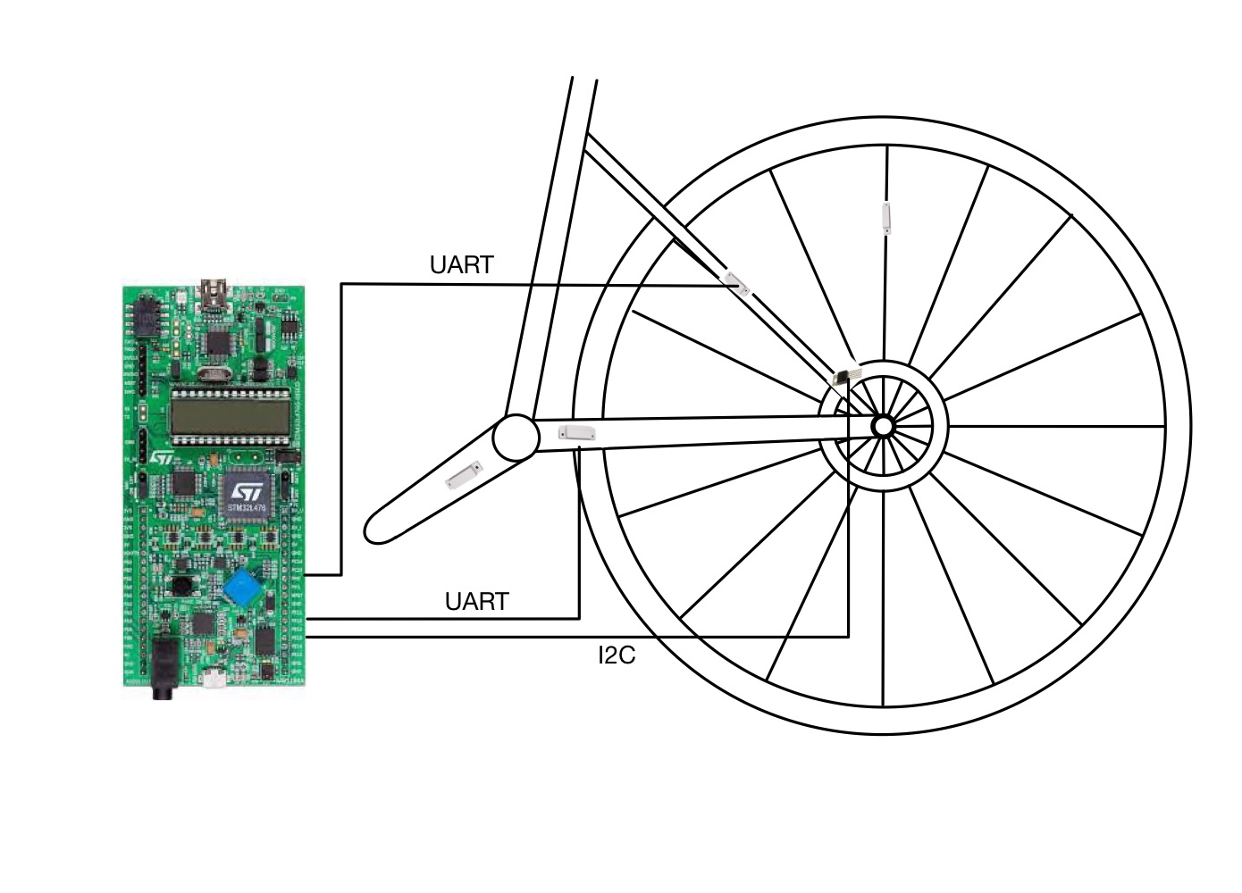
The goal of this project is to use the STM32L4 Discovery Board and peripheral sensors to gather and display data from a bicycle that is pertinent to the cyclist. Specifically, the cyclist’s speed, pedal cadence , and brake temperature are read by the peripheral sensors and displayed on the Discovery Board’s built in LCD.
Speed and cadence is measured in the same way, with two-piece proximity sensors magnets and reed switches to measure revolution speed. One part of the sensor The reed switches are mounted on the bicycle frame and its counterpart the magnet is mounted on the wheel in the case of speed measurement, and on the pedal crank arm in the case of cadence measurement. Both of these peripherals are interfaced with UART to communicate with the microcontroller the microcontroller’s on board timers.
Brake temperature is measured using the TC-74 temperature mounted on the bicycle frame in close proximity to the brake rotor. This information helps inform the cyclist whether or not it’s safe to touch the brake system, if, for instance, any maintenance is required. This peripheral communicates with the microcontroller through I2C serial interfacing.
These three two measurements are displayed on the Discovery Board’s LCD, with the built in joystick allowing the cyclist to page through them.
Block Diagram
Weekly Updates
Final Update 03/18/2021
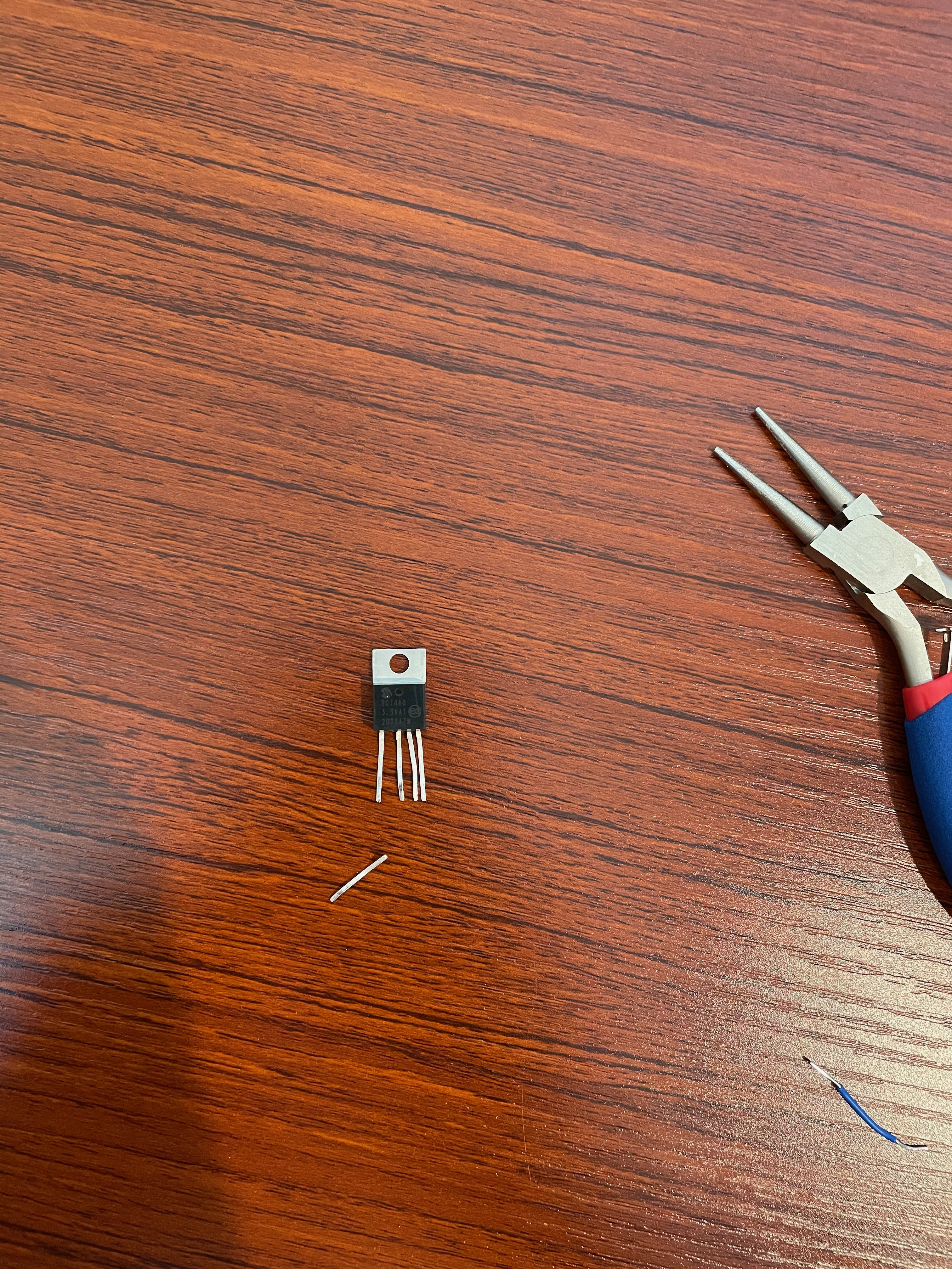
I finished my project yesterday afternoon and filmed the demo video with help from my housemate. The speed and cadence sensors work as expected, however I wasn’t able to implement the temperature sensor into the project. The SDA pin on the sensor broke clean off while I was trying to wire it on the last day, so I had no time to order a replacement. The code for the sensor is included in the project, but all the initializations and calculations relying on the sensor are commented out.
The speed and cadence sensors work in almost identical ways, albeit different math to calculate the appropriate values for each. They both use TIM4 of the Discovery Board operating at 1 MHz in input capture mode to calculate the time for a full rotation in microsseconds. There are two magnets, one attatched to the spokes of the rear wheel and one to the pedal crank arm, that will close their respective circuits and trigger an interrupt in the corresponding timer channel.
The biggest challenges I faced in this project centred mostly around getting the project on the bike. All the circuitry had to be reasonably durable so as not to fall apart if the road gets a little bumpy. It took most of a day to wire everything in a way that it would hold up on a bike ride, and such that the two circuits would not interfere with one another. Powering the project was also a bit of a challenge. I wasn’t able to get the microcontroller to operate on battery power with a CR2032 watch battery, so I ended up powering it via USB using a portable battery bank.
One thing I would change about the design is to include a real time clock to update the measurements if they haven’t been by the reed switches in a while. This is less a problem with speed, as often a cyclist will roll to a stop and the speed will continue to update as wheel continues to spin. However it is certainly an issue with the cadence measurement, as going from 90 rpm to coasting would result in the LCD displaying 90 rpm until the cyclist began to pedal again.
Week of 03/08/2021 - 03/14/2021
- Import and adapt project code
- Debug TC74 Temperature sensor interface
- Research how to interface reed switches and Discovery Board via Bluetooth
Week of 03/01/2021 - 03/07/2021
- Finish reseaching appropriate proximity sensor
- Finalize project plan to satisfy requirements
- Establish project organization
-
Order all necessary parts
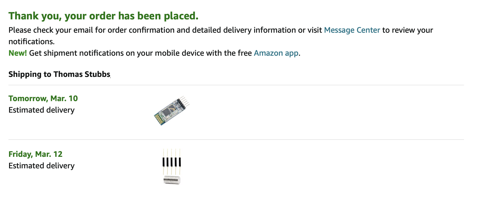
Decided to implement the speed and cadence sensors with simple reed swithces mounted to the bicycle frame with magnets attatched to the spoke/pedal crank arm. Both of these will communicate with the STM32L476VG Discovery Board using the microcontroller’s built in timer channels operating in the capture mode. Since this is not a serial communication protocol, I’ve also purchased an additional HC-05 Bluetooth module to see if I can get the sensors to interface with the microcontroller wirelessly via UART and Bluetooth.
Week of 02/22/2021 - 02/28/2021
- Discuss with TA’s/Instructors about appropriate proximity sensors for this project.
- Order required equipment (proximity sensors, wires)
-
Explore Soldering for implementation
Still looking into hall effect sensor vs reed switch for measuring speed/cadence. From what I gather, they’re a simpler type of sensor than I anticipated, interfacing with voltage/current pulses rather than digital data interfacing. I’ll need to explore other ideas with this project in order to meet the required 2 different serial communication protocols. Next week will be focused on finishing up more detailed research on how to implement this project under the requirements and establishing the project organization.